miércoles, 21 de octubre de 2015


Arduino based humidity and Temperature real time reading displayed on a 16x2 LCD display


Sebastian Wolter
21-10-2015


Hello everyone, this time i will show you a very simple but fun real time temperature and humidity display, this one displays the information in a 16x2 lcd display, as show in the following imge:


As you can see it looks really cool. Now, to build this little gadget you will need:

- Arduino board (I used and UNO model).
- A power supply for the board (Can be AC-DC 9 v power supply, a pack of AA batteries, etc).
- One Humidity and Temperature sensor (I used the DHT11).
- DHT11 (in this case) Library, can get it from GitHUB: https://github.com/adafruit/DHT-sensor-library
- One 4.7 Kohm resistor.
- One 16x2 LCD Display (Or can be a bigger one also, or even a TFT based display).  
- One half size + Breadboard (or bigger).
- Several cables to make the connections.

One you have all the parts, you need to do the wiring, which is shown in the following picture:


The wiring is as described below:

Potentiometer:
GND to GND
VCC to +5V
Signal goes to Display pin # 3

DHT11 sensor (Temperature and humidity):
GND to GND
VCC to +5V
Signal goes to Arduino digital pin # 7

LCD Display 16x2:
Pin # 1 goes to GND
Pin # 2 goes to + 5V
Pin # 3 goes to POT
Pin # 4 goes to Arduino Digital pin # 12
Pin # 5 goes to GND
Pin # 6 goes to Arduino Digital pin # 11
Pin # 11 goes to Arduino Digital pin # 5
Pin # 12 goes to Arduino Digital pin # 4
Pin # 13 goes to Arduino Digital pin # 3
Pin # 14 goes to Arduino Digital pin # 2
Pin # 15 goes to +5V through the 4.7 ohm resistor
Pin # 16 goes to GND

The Temperature and Humidity sensor i used is the model DHT11, which look like this:


In order to use this device inside your sketches on the arduino IDE, you have to download and copy its library to the libraries folder in your local arduino IDE installation.
Once you have downloaded the library, you need to put it inside the arduino IDE libraries folder, just like this:


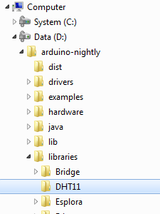
 And put the both .CPP and .H files inside the folder named DHT11, like this:


If you verify the sketch inside the arduino IDe and get error aboout the library, go to:

Sketch  -> Include Library -> And select the DHT library (You should see it there, if not, restart the IDE):


Once everything is correctly wired, and the library has been added to the arduino IDE and your Compile/Verify is OK, you have to upload the arduino sketch to your board, the original code is to display the "Hello World" phrase on a LCD display, i just have modified it a bit to add the temp and humidity sensor reading and display it on the LCD screen instead of the "Hello World" phrase.

The sketch code is as follows:

/*
  LiquidCrystal Library
 Demonstrates the use a 16x2 LCD display.  The LiquidCrystal
 library works with all LCD displays that are compatible with the
 Hitachi HD44780 driver. There are many of them out there, and you
 can usually tell them by the 16-pin interface.


  The circuit:
 * LCD RS pin to digital pin 12
 * LCD Enable pin to digital pin 11
 * LCD D4 pin to digital pin 5
 * LCD D5 pin to digital pin 4
 * LCD D6 pin to digital pin 3
 * LCD D7 pin to digital pin 2
 * LCD R/W pin to ground
 * LCD VSS pin to ground
 * LCD VCC pin to 5V
 * 10K resistor:
 * ends to +5V and ground
 * wiper to LCD VO pin (pin 3)

 Library originally added 18 Apr 2008
 by David A. Mellis
 library modified 5 Jul 2009
 by Limor Fried (http://www.ladyada.net)
 example added 9 Jul 2009
 by Tom Igoe
 modified 22 Nov 2010
 by Tom Igoe

 This example code is in the public domain.

 http://www.arduino.cc/en/Tutorial/LiquidCrystal
 */

// include the library code:
#include <LiquidCrystal.h>
#include <DHT.h>
#define DHTPIN 7
#define DHTTYPE DHT11
DHT dht(DHTPIN, DHTTYPE);
// initialize the library with the numbers of the interface pins
LiquidCrystal lcd(12, 11, 5, 4, 3, 2);

void setup() {
  dht.begin();
  // set up the LCD's number of columns and rows:
  lcd.begin(16, 2);
  // Print a message to the LCD.
  //lcd.print("hello, world!");
  Serial.begin(9600);
}

void loop() {
  float h = dht.readHumidity();// Lee la humedad
  float t = dht.readTemperature(); //Lee la temperatura
  Serial.println("Humedad: ");
  Serial.println(h);
  Serial.println("Tempera: ");
  Serial.println(t);
  // set the cursor to column 0, line 1
  // (note: line 1 is the second row, since counting begins with 0):
  lcd.setCursor(0,0);
  lcd.print("Temperatur");
  lcd.setCursor(11, 0);
  lcd.print(t);

  lcd.setCursor(0,1);
  lcd.print("Humedad");
  lcd.setCursor(11, 1);
  lcd.print(h);
  // print the number of seconds since reset:
  //lcd.print(millis() / 1000);
}


The sketch ".ino" source code an be downloaded from here: Arduino Sketch File

DHT11 library can be downloaded from here: DHT11 arduino library code files

Enjoy!

viernes, 16 de octubre de 2015

qt c++ based - serial communications MeArm robotic arm controller

Sebastian Wolter
16-10-2015

Good morning everyone
This is my first publication so is very special because of that, and y hope to be clear in the explanations and to be able to help others which are starting into this fascinating arduino based electronics and robotics, which also covers some of C++ programming.

Today i will present a very little and simple QT C++ based program to control the OpenSource MeARM robotic Arm using serial communications library.


The MeARM sources and build instructions can be found in the following link:

Instructables - MeARM

Once your arm has been fully assembled and tuned for free proper motion, you need to wire it all agains your arduino board, which in my case is an Arduino UNO.

The next image shows the wiring between the meArm and the Arduino Board:


Base Servo connects to pin 11
Left Servo connects to pin 10
Right servo connects to pin 9
Claw servo connects to pin 6

You can also make the use of an arduino sensor shield to facilitate conections, if you can get one is ok.

Once you have everything wired, you have to upload the arduino sketch to the arduino board, the following is the arduino sketch code used:


#include <Servo.h>

//MeArm HAS 4 SERVOS
Servo xServo;  // create servo object, arm base servo - left right motion
Servo yServo;  // create servo object, left side servo - forward backwards motion
Servo zServo;  // create servo object, right side servo - forward backwards motion
Servo clawServo;  // create servo object, end of arm srevo - open,close the claw hand

//servo positions values, expects 1-180 deg.
int xPos;
int yPos;
int zPos;
int clawPos;

//*************** INIT AT STARTUP *******************************************************************

void setup() {        // the setup function runs once when you press reset or power the board

  // assign servo to pin numbers
  xServo.attach(11);  // attaches the servo on pin 11 to the servo object
  yServo.attach(10);  // attaches the servo on pin 10 to the servo object
  zServo.attach(9);  // attaches the servo on pin 9 to the servo object
  clawServo.attach(6);  // attaches the servo on pin 6 to the servo object

  // initialize serial port
  Serial.begin(9600);

  // Debug only send serial message to host com port terminal window in Arduino IDE
  //Serial.print("*** MeCom Test V04 ***.");   // send program name, uncomment for debug connection test

xServo.write(90);
yServo.write(90);
zServo.write(90);
clawServo.write(90);

}

// ******************************************************************************************************
// ********************************** MAIN PROGRAM LOOP START *******************************************
// ******************************************************************************************************


void loop() {
  //serial in packet patern = xVal,yVal,zVal,clawVal + end of packet char 'x'
  while (Serial.available() > 0) {
    xPos = Serial.parseInt();
    yPos = Serial.parseInt();
    zPos = Serial.parseInt();
    clawPos = Serial.parseInt();
   
    if (Serial.read() == 'x') { // Detect end of packet char 'x', go ahead and update servo positions
      // UPDATE SERVO POSITIONS
      xServo.write(xPos);
      yServo.write(yPos);
      zServo.write(zPos);
      clawServo.write(clawPos);
    }
  }
}


 sketch code can be downloaded here:  sketch ino

The arduino Sketch was not written by myself, it came along with the MeArm kit i bought from amazon.

The Sketch expects to receive a formatted string with a special character 'x' denoting the end of the string, as follows:

xPos,yPos,zPos,clawPosx

Which could be something like this:

90,90,90,40x

Last character 'x' tells the program the end of the string and to write down the vlaues to the corresponding servo motors.

In my particular case i have found that the claw fully opens and closes between 10 and 40 degrees positions in the servo, being 40 fully closed and 10 fully open, so this can be different in your own arm, you can easily modify the sketch to accomplish your particular setting in the following line:

clawServo.write(90);

And put it according to your arm claw close position, like this:

clawServo.write(40);

Final step is to open the QT project, i used QT with MinGW (gc++), the following version:


Which can be downloaded from here -> http://www.qt.io/download-open-source/#section-2

Once QT is installed, we may open the project: QT project Source


The program basically has 4 sliders to control each one of the servos, as stated before my particular claw setting are from 10 to 40 degrees only on Claw Servo, you can modifiy the program to suite your desing.


Once you run the program:


 Remember to connect your arduino board using the usb cable to your computer and select the correct COM port to use the applications.
The application is an in-progress work, but the basic arm functions are working great.

Hope it can help somebody.........


Sebastian Wolter
Octubre 2015
Control de brazo robótico MeArm via Serial con programa en QT

Sebastian Wolter
16-10-2015

Buenos días con todos.
Este es mi primera publicación, por lo tanto es muy especial en ese sentido y por lo mismo espero ser claro en la explicación y poder ayudar a todos los aficionados a la robótica y programación que estén dando sus primeros pasos.

El dia de hoy les presento un sencillo programa realizado con el ide QT y programado con C++ para controlar via puerto serial el MeARM.


Las instrucciones de ensamblado del MeARM así como su fuente las pueden encontrar en:

Instructables - MeARM

Una vez armado y ajustado correctamente el brazo robotico, vamos a conectarlo a nuestra placa arduino, en mi caso, un arduino UNO.

La siguiente grafica muestra la conexion realizada entre el brazo y la placa:


El servo de la base se conecta al pin 11
El servo del lado izquierdo se conecta al pin 10
El servo del lado derecho se conecta al pin 9
El servo de la pinza se conecta al pin 6

También se puede hacer el uso de un sensor shield para el arduino, para facilitar la conexión, si es que lo disponen.

Una vez conectado todo, vamos a cargar el sketch a nuestro arduino, el código del sketch es el siguiente:


#include <Servo.h>

//MeArm HAS 4 SERVOS
Servo xServo;  // create servo object, arm base servo - left right motion
Servo yServo;  // create servo object, left side servo - forward backwards motion
Servo zServo;  // create servo object, right side servo - forward backwards motion
Servo clawServo;  // create servo object, end of arm srevo - open,close the claw hand

//servo positions values, expects 1-180 deg.
int xPos;
int yPos;
int zPos;
int clawPos;

//*************** INIT AT STARTUP *******************************************************************

void setup() {        // the setup function runs once when you press reset or power the board

  // assign servo to pin numbers
  xServo.attach(11);  // attaches the servo on pin 11 to the servo object
  yServo.attach(10);  // attaches the servo on pin 10 to the servo object
  zServo.attach(9);  // attaches the servo on pin 9 to the servo object
  clawServo.attach(6);  // attaches the servo on pin 6 to the servo object

  // initialize serial port
  Serial.begin(9600);

  // Debug only send serial message to host com port terminal window in Arduino IDE
  //Serial.print("*** MeCom Test V04 ***.");   // send program name, uncomment for debug connection test

xServo.write(90);
yServo.write(90);
zServo.write(90);
clawServo.write(90);

}

// ******************************************************************************************************
// ********************************** MAIN PROGRAM LOOP START *******************************************
// ******************************************************************************************************


void loop() {
  //serial in packet patern = xVal,yVal,zVal,clawVal + end of packet char 'x'
  while (Serial.available() > 0) {
    xPos = Serial.parseInt();
    yPos = Serial.parseInt();
    zPos = Serial.parseInt();
    clawPos = Serial.parseInt();
   
    if (Serial.read() == 'x') { // Detect end of packet char 'x', go ahead and update servo positions
      // UPDATE SERVO POSITIONS
      xServo.write(xPos);
      yServo.write(yPos);
      zServo.write(zPos);
      clawServo.write(clawPos);
    }
  }
}


Enlace del sketch:  sketch ino

El sketch de arduino no es de mi autoría y debo decirlo lo adquirí con un kit de brazo robótico MeARM comprado a través de amazon.

El programa espera recibir via serial una cadena conformada de la siguiente manera:

xPos,yPos,zPos,clawPosx

Que podría ser:

90,90,90,40x

El ultimo caracter 'x' indica al programa que es el fin de la cadena y que escriba los datos correspondientes a cada uno de los servos.

En mi caso, la pinza abre y cierra perfectamente entre 10 y 40 grados, es por ello, que podriamos modificar la siguiente linea del sketch:

clawServo.write(90);

Y ponerla de acuerdo a los limites de nuestro propio brazo asi:

clawServo.write(40);

En mi caso, 40 seria la posicion cerrada de la pinza. Los demas servos con un valor incicial de 90 (centro) estarian bien.

El paso final, es cargar el programa en el ide QT y compilarlo. Yo use el IDE QT con el compilador MinGW (gc++), la siguiente version:


que se lo pueden descargar de aqui -> http://www.qt.io/download-open-source/#section-2

Una vez instalado QT, abrimos el proyecto: codigo fuente proyecto QT


El programa tiene sliders para manejar la base, servos izquierdo y derecho asi como para la pinza.
Como mencione anteriormente, en mi caso particular, la pinza se abre y cierra completamente desde los 10 hasta los 40 grados de giro del servo, por lo tanto el programa esta con esos parámetros, pero pueden ser cambiados a gusto.

Una vez compilado el programa, al ejecutarlo:


 Recuerden tener conectada la placa arduino via puerto serial al PC, el programa buscara ls puertos COM y se podra conectar a la placa arduino.
El programa esta aun en desarrollo, pero ya tiene completamente funcionales las opciones basicas de manejo del brazo robotico, ademas de poder guardar y abrir archivos con rutas de movimientos y reproducirlas en forma automatica.

Espero les sea de utilidad.......

Sebastian Wolter
Octubre 2015